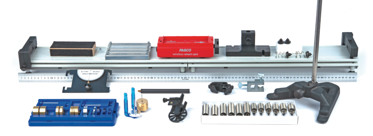
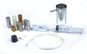
The laboratory portion of the College Board AP® Physics 2 course is a key factor in preparing students for the AP Physics 2 exam. For students, these practical activities help link theoretical concepts to real-life situations while also arming them with the scientific inquiry, logical reasoning, and analytical thinking skills to excel in college science courses.
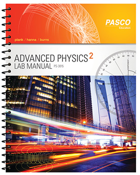
Advanced Physics 2 Lab Manual
Help students tie theory to practice with sixteen guided inquiry labs for AP Physics 2.
Authored by physics educators, the Advanced Physics 2 Lab Manual includes sixteen guided inquiry labs that cover AP Physics 2 topics such as fluid dynamics, optics, interference and diffraction, magnetic fields, electricity, RC Circuits, and Planck’s Constant.
AP Physics 2 Course Alignment
Each investigation addresses at least one Learning Objective and Science Practice for Advanced Placement® Physics 2, as outlined in the College Board AP® Physics 2: Algebra-Based Course and Exam Description.
This page provides AP Physics 2 alignment details for the labs inside PASCO’s Advanced Physics 2 Lab Manual. A complete list of applicable AP Physics 2 Big Ideas, Learning Objectives, and Science Practices is provided for each lab. High school alignment details, including NGSS-alignment details, can be found inside the Teacher Guide included with each lab.
Need a quick guide?
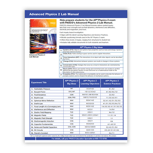
Download the AP Physics 2 Alignment Sheet.
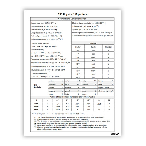
Download the Equation Sheet for AP Physics 2.
Advanced Physics 2 Lab Manual Lab Titles
| 1 - Hydrostatic Pressure | 9 - Electric Field Mapping |
| 2 - Buoyant Force | 10 - Magnetic Fields |
| 3 - Fluid Dynamics | 11 - Magnetic Field Strength |
| 4 - Boyle’s Law | 12 - Electromagnetic Induction |
| 5 - Spherical Mirror Reflection | 13- Capacitor Fundamentals |
| 6 - Snell’s Law | 14 - Series and Parallel Capacitors |
| 7 - Focal Length of a Converging Lens | 15 - RC Circuits |
| 8 - Interference and Diffraction | 16 - Planck’s Constant |
| Three Levels of Scientific Inquiry | |
|
Every lab is provided in three formats—Structured, Guided Inquiry, and Student Designed—allowing you to choose the level of inquiry that’s right for your physics course. All versions include identical Analysis and Synthesis Questions that reflect questions posed on the AP Physics 2 exam.
|
|
Hydrostatic Pressure
How is static pressure related to depth in a column of water? In this investigation, students use a Wireless Pressure Sensor to measure the static pressure at different depths in a column of water and use their data to determine the mathematical relationship between static pressure and depth in a fluid.
| Prerequisites |
|
| Big Idea | Force Interactions (INT) |
| Learning Objectives |
3.C.4.1: Make claims about various contact forces between objects based on the microscopic cause of those forces. 3.C.4.2: Explain contact forces (tension, friction, normal, buoyant, spring) as arising from interatomic electric forces and that they therefore have certain directions. |
| Science Practices | 6.1, 6.2 |
Teaching Tools
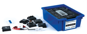
Physics Lab Stations
Explore all of Physics 2—plus many topics from AP Physics 1— with our expandable Physics Lab Stations.Buoyant Force
In this hands-on lab, students use the Smart Cart’s force sensor to measure the buoyant force on a metal cylinder as it’s lowered into a fluid. Then, they determine the relationship between the buoyant force and a) its volume and b) the weight of the fluid displaced by the submerged object.
| Prerequisites |
|
| Big Ideas |
Systems (SYS) Force Interactions (INT) |
| Learning Objectives |
1.E.1.2: Select from experimental data the information necessary to determine the density of an object and/or compare densities of several objects. 3.C.4.2:Explain contact forces (tension, friction, normal, buoyant, spring) as arising from interatomic electric forces and that they therefore have certain directions. |
| Science Practices | 4.1, 6.2, 6.4, 7.2 |
Fluid Dynamics
How does the height of a fluid column relate to the exit velocity of the fluid at the bottom of the column? This lab challenges students to uncover the answer experimentally using a water reservoir, basin, and a meter stick.
| Prerequisites |
|
| Big Idea | Conservation (CON) |
| Learning Objectives |
5.B.10.1: Make calculations related to a moving fluid using Bernoulli’s equation. 5.B.10.3: Make calculations related to a moving fluid using Bernoulli’s equation and the continuity equation. 5.B.10.4: Construct an explanation of Bernoulli’s equation in terms of the conservation of energy. |
| Science Practices | 2.2, 6.2 |
Teaching Tools
Physics Lab Station: Fluids
Investigate fluid dynamics, buoyant force, and Boyle’s law with Physics Lab Station: Fluids.Boyle’s Law
In this hands-on investigation, students investigate Boyle’s law using a pressure sensor and a syringe. They create plots of pressure versus volume and analyze their results to determine the inverse proportionality between the pressure and volume of an enclosed gas.
| Prerequisites |
|
| Big Ideas |
Conservation (CON) Probability (PRO) |
| Learning Objectives |
5.B.7.2: Create a plot of pressure versus volume for a thermodynamic process from given data. 7.A.3.2: Design a plan for collecting data to determine the relationships between pressure, volume, and temperature, and/or the amount of an ideal gas; and to refine a scientific question proposing an incorrect relationship between the variables. 7.A.3.3: Analyze graphical representations of macroscopic variables for an ideal gas to determine the relationships between these variables and to ultimately determine the ideal gas law $ PV = nRT $. |
| Science Practices | 1.1, 3.2, 4.2, 5.1 |
Spherical Mirror Reflection
How can we determine the radius of curvature for a mirror? In this experiment, students use an optics light source, optics track, and a half screen to measure the image and object distances associated with the real image formed by a concave spherical mirror. They apply the principles of reflection and the spherical mirror equation to determine the mirror’s radius of curvature.
| Prerequisites |
|
| Big Idea | Waves (WAV) |
| Learning Objectives |
6.E.4.1: Plan data collection strategies and perform data analysis and evaluation of evidence about the formation of images due to reflection of light from curved spherical mirrors. 6.E.4.2: Use quantitative and qualitative representations and models to analyze situations and solve problems about image formation occurring due to the reflection of light from surfaces. |
| Science Practices | 3.2, 4.1, 4.2, 5.1, 5.2, 5.3 |
Teaching Tools
Physics Lab Station: Optics
Support student studies of optics concepts—ranging from focal length to Snell’s law—with Physics Lab Station: Optics.Snell’s Law
In this lab investigation, students apply the principles of refraction and Snell's law to experimentally determine the index of refraction of a transparent medium. They use a Basic Optics Ray Table to measure the incident and refraction angles of a light ray traveling from air into a material with an unknown index of refraction.
| Prerequisites |
|
| Big Idea | Waves (WAV) |
| Learning Objectives |
6.E.3.2: Plan data collection strategies as well as perform data analysis and evaluation of the evidence for finding the relationship between the angle of incidence and the angle of refraction for light crossing boundaries from one transparent material to another (Snell’s law). 6.E.3.3: Make claims and predictions about path changes for light traveling across a boundary from one transparent material to another at non-normal angles resulting from changes in the speed of propagation. |
| Science Practices | 4.1, 5.1, 5.2, 5.3, 6.4, 7.2 |
Focal Length of a Converging Lens
How can we calculate the focal length of a lens? In this hands-on investigation, students measure the image and object distances associated with the real image formed by a converging lens, and then determine the focal length of the lens.
| Prerequisites |
|
| Big Idea | Waves (WAV) |
| Learning Objectives |
6.E.5.1: Use quantitative and qualitative representations and models to analyze situations and solve problems about image formation occurring due to the refraction of light through thin lenses. 6.E.5.2: Plan data collection strategies, perform data analysis and evaluation of evidence, and refine scientific questions about the formation of images due to refraction for thin lenses. |
| Science Practices | 1.4, 2.2, 3.2, 4.1, 5.1, 5.2, 5.3 |
Teaching Tools
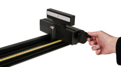
PASCO Basic Optics System
Discover the PASCO Basic Optics System—a durable optics system that expands to meet your needs.Interference and Diffraction
How can the wave nature of light be used to determine the distance between two closely-spaced narrow parallel slits? In this laboratory investigation, students experimentally determine the spacing between the slits in a double-slit aperture using a coherent light source and the principles associated with double-slit interference and diffraction.
| Prerequisites |
|
| Big Idea | Waves (WAV) |
| Learning Objective |
6.C.3.1: Qualitatively apply the wave model to quantities that describe the generation of interference patterns to make predictions about interference patterns that form when waves pass through a set of openings whose spacing and widths are small compared with the wavelength of the waves. |
| Science Practices | 1.4, 6.4 |
Teaching Tools
Wireless Diffraction System
Want picture-perfect diffraction patterns every time? Explore the PASCO Wireless Diffraction System and see the difference!Electric Field Mapping
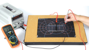
How can the characteristics of the electric field surrounding oppositely-charged electrodes in two dipole and parallel plates be determined experimentally? In this hands-on experiment, students use a DC power supply and semi-conductive paper to create dipole and parallel plate electrodes. They then use the principles of electric fields and electric potential energy to determine the shape and direction of the electric field lines in each configuration.
| Prerequisites |
|
| Big Idea | Fields (FLD) |
| Learning Objective |
2.E.2.1: Determine the structure of isolines of electric potential by constructing them in a given electric field. |
| Science Practices | 6.4, 7.2 |
Teaching Tools
Field Mapper Kit
Help students visualize electric fields more easily with the Field Mapper Kit.Magnetic Fields
How do the characteristics of the magnetic field created by a bar magnet and a current-carrying coil differ? In this lab, students use an AC/DC Electronic Laboratory, power supply, and a Magnaprobe™ wand to determine the shape and direction of the magnetic fields created by a bar magnet and a current-carrying coil. Then they compare the two and identify distinct differences and similarities between them.
| Prerequisites |
|
| Big Idea | Fields (FLD) |
| Learning Objectives |
2.D.2.1: Create a verbal or visual representation of a magnetic field around a straight wire or a pair of parallel wires. 2.D.3.1: Describe the orientation of a magnetic dipole placed in a magnetic field in general and the particular cases of a compass in the magnetic field of Earth and iron filings surrounding a bar magnet. 2.D.4.1: Qualitatively analyze the magnetic behavior of a bar magnet composed of ferromagnetic material. |
| Science Practices | 1.1, 1.2, 1.4 |
Teaching Tools
Physics Lab Station: Electricity and Magnetism
Engage students in the exploration of magnetic and electric fields with Physics Lab Station: Electricity and Magnetism.Magnetic Field Strength
How is the strength of the magnetic field at the center of a current-carrying coil dependent on the coil current and radius? In this hands-on investigation, students use a 3-axis Magnetic Field Sensor and the AC/DC Electronics laboratory to determine the mathematical relationship between the current, radius, and the magnetic field at the center of the current-carrying coil.
| Prerequisites |
Students should be familiar with these concepts:
|
| Big Idea | Fields (FLD) |
| Learning Objective |
2.D.2.1: Create a verbal or visual representation of a magnetic field around a straight wire or a pair of parallel wires. |
| Science Practices | 1.1 |
Teaching Tools
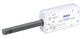
Wireless Magnetic Field Sensor
Easily measure the strength of magnetic fields—whether they be from the Earth or a current-carrying wire—with the Wireless Magnetic Field Sensor.Electromagnetic Induction
In this laboratory investigation, students use a voltage sensor to measure the maximum emf induced in a coil as a permanent magnet is dropped through it. They vary the number of loops in the coil and determine how the rate of change of magnetic flux through the coil affects both the magnitude and direction of the induced emf.
| Prerequisites |
|
| Big Idea | Change (CHA) |
| Learning Objective |
4.E.2.1: Predict which properties determine the motion of a simple harmonic oscillator and what the dependence of the motion is on those properties.Construct an explanation of the function of a simple electromagnetic device in which an induced emf is produced by a changing magnetic flux through an area defined by a current loop (i.e., a simple microphone or generator) or of the effect on behavior of a device in which an induced emf is produced by a constant magnetic field through a changing area. |
| Science Practices | 6.4 |
Teaching Tools
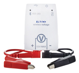
Wireless Voltage Sensor
Help students safely explore electrical concepts with real-time data from the Wireless Voltage Sensor.Capacitor Fundamentals
In this investigation, students construct capacitors from paper and aluminum foil and use a digital capacitance meter to determine how the physical properties of a parallel-plate capacitor affect its ability to store electric charge.
| Prerequisites |
|
| Big Idea | Change (CHA) |
| Learning Objectives |
4.E.4.2: Design a plan for the collection of data to determine the effect of changing the geometry and/or materials on the resistance or capacitance of a circuit element, and relate results to the basic properties of resistors and capacitors. 4.E.4.3: Analyze data to determine the effect of changing the geometry and/or materials on the resistance or capacitance of a circuit element, and relate results to the basic properties of resistors and capacitors. |
| Science Practices | 4.1, 4.2, 5.1 |
Product Guide
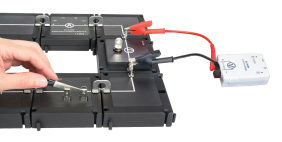
Modular Circuits
Skip the wires and get right to the learning with circuit components that mirror textbook models!Series and Parallel Capacitors
In this investigation, students use a capacitance meter to measure the equivalent capacitance in simple circuits—both in series and in parallel—before determining the equivalent capacitance of capacitors connected in series and parallel.
| Prerequisites |
|
| Big Ideas |
Change (CHA) Conservation (CON) |
| Learning Objectives |
4.E.5.3: Plan data collection strategies and perform data analysis to examine the values of currents and potential differences in an electric circuit that is modified by changing or rearranging circuit elements, including sources of emf, resistors, and capacitors. 5.B.9.5: Describe and make predictions regarding electrical potential difference, charge, and current in steady state circuits composed of various combinations of resistors and capacitors using conservation of energy principles (Kirchhoff’s loop rule). |
| Science Practices | 2.2, 4.2, 5.1, 6.4 |
RC Circuits
This experiment engages students in the exploration of RC circuits using a voltage sensor, current sensor, and the AC/DC Electronics Laboratory. Students construct an RC circuit and determine how the potential differences across the resistors and capacitor change when the capacitor is charging, discharging, or fully charged. Then they determine how these differences alter the current that flows through the various circuit components.
| Prerequisites |
|
| Big Idea | Change (CHA) |
| Learning Objectives |
4.E.5.1: Make and justify a quantitative prediction of the effect of a change in values or arrangements of one or two circuit elements on the currents and potential differences in a circuit containing a small number of sources of emf, resistors, capacitors, and switches in series and/or parallel. 4.E.5.2: Make and justify a qualitative prediction of the effect of a change in values or arrangements of one or two circuit elements on currents and potential differences in a circuit containing a small number of sources of emf, resistors, capacitors, and switches in series and/or parallel. 4.E.5.3: Plan data collection strategies and perform data analysis to examine the values of currents and potential differences in an electric circuit that is modified by changing or rearranging circuit elements, including sources of emf, resistors, and capacitors. |
| Science Practices | 2.2, 4.2, 5.1, 6.1, 6.4 |
Teaching Tools
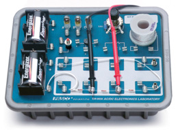
AC/DC Electronics Laboratory
Introduce the fundamentals of basic circuitry with our complete AC/DC Electronics Laboratory.Planck’s Constant
What is the value of Planck's constant and how can it be determined experimentally? In this lab investigation, students use a voltage sensor and the AC/DC Electronics Laboratory to measure the voltage required to turn on variously colored LEDs. They create plots of turn-on voltage vs. LED frequency and determine the value of Planck’s constant.
| Prerequisites |
|
| Big Idea | Waves (WAV) |
| Learning Objectives |
6.F.3.1: Support the photon model of radiant energy with evidence provided by the photoelectric effect. 6.F.4.1: Select a model of radiant energy that is appropriate to the spatial or temporal scale of an interaction with matter. |
| Science Practices | 6.4, 7.1 |

